Round wood and lumber
Loading and unloading of logs, logs, poles, lumber and sleepers should be carried out mechanized way or using special devices of small mechanization. Manual loading and unloading of these goods, except for impregnated sleepers, is allowed in exceptional cases, subject to all requirements ensuring the safety of work under the supervision of a responsible person.
Before starting unloading roundwood in all cases, the supervisor must personally inspect the condition of each pile, paying particular attention to the position of the “cap”, give instructions on the procedure for unloading and appoint a responsible person. In cases where the roundwood stacks on the wagons are unstable (skew, broken racks, unreliable average linkage), the work manager supervises the work until the end of unloading.
A) the boom of the crane corresponded to the weight of the load to be lifted;
B) the building of logs loaded using the upper narrowed part of the outline of loading with a “cap” was made from the stairs;
C) in gondola cars, safety racks were installed in the gaps between the side and the stack to a depth of at least 0.75 m close to the main racks and secured with a wooden wedge;
D) on the platforms, the safety posts were secured with ties of the required strength, twisted from wire into two threads with loops at the ends.
If the weight of the “cap” does not exceed the carrying capacity of the machine, it can be unloaded in one go without removing the wire link.
If the weight of the “cap” is greater than the capacity of the crane, it must be unloaded in parts. In this case, three safety posts with a height of 0.3 m above the top level of the stack should be installed on each side of the stack.
It is forbidden to be in gondola cars and cars when lifting and lowering cargo.
When opening the sides of the platforms, cutting off the tie wire, removing the racks, workers are not allowed to be in the zone of a possible drop in cargo.
In the points of unloading of round and sawn timber with lifting cranes, they should be laid perpendicular to the axis of the path in the cells fenced on each side by two columns, or in special racks. The width of the cells, shelving should be 3 m, the height of the stack - not more than 3 m, the aisles between the cells, shelving - not less than 1 m.
Heavy cargo
133. Heavy loads weighing more than 500 kg in one place are moved during loading and unloading only with the help of lifting machines.The most experienced workers should be assigned to work with heavy and bulky goods.
134. Before the loading and unloading of heavy cargoes, the work manager must explain to the workers the procedure and sequence of operations, make sure the slings and other devices are in good working order. When loading and unloading goods that are close in weight to the nominal carrying capacity of the mechanism, especially bulky and oversized cargoes, the work manager must supervise the work until its completion.
The loading and unloading of rails and metal beams should be carried out mechanically. In exceptional cases, it is allowed to carry out work with the specified cargo on a bed of rails or logs in compliance with safety requirements.
Reinforced concrete products must be unloaded mechanically and placed on linings and gaskets:
foundation blocks and basement wall blocks - into a stack of not more than 2.6 m high;
wall blocks - in a stack in two tiers;
floor slabs - in a stack with a height of not more than 2.5 m ^
crossbars and columns - in, a stack up to 2 m high.
Turning over of heavy cargoes is allowed to be carried out on a specially designated site, in the presence of a work manager.
Bulk loading or unloading of vehicles with self-propelled vehicles should be carried out from end platforms with inclined descents;
Containers
The arrangement of containers on the container site should be carried out in compliance with the dimensions established by the Rules of technical operation
railways of the USSR, and the Rules for the design and safe operation of cranes.
The gap between the containers on the site should be at least 0.1 m.
Between groups of containers on the site there must be passages at least 1 m wide.
Car rides are arranged depending on the types of material handling machines.
When loading and unloading containers, the following requirements must be observed:
B) to place loaded or empty containers in one tier on a free place free of foreign objects ;, heavy containers in the presence of autotrops may be installed in two and three tiers;
C) to load two containers only in the presence of load-lifting traverse;
D) to store containers on the site in rows located perpendicular to the crane way with the doors inward.
Loading and unloading of containers should be carried out with the help of devices and devices that allow fully or partially to automate the sling and sling of containers.
To move the strollers on the cranes, platforms and transitional bridges should be provided.
Packing (non-toxic) cargo
Processing of packaging materials in warehouses and cargo sorting platforms should be carried out using electric forklifts and pallets.
In some cases, it is allowed to move packaging materials manually using small-scale mechanization.
Loads in crates, bales, bales should be stacked in stable stacks both in the wagon during loading and in the warehouse when unloading.
Loads in bags and stools should be stacked in dressings, after every 6 rows laying from the boards is done. The container must be in good condition.
149. Loads in barrels, drums and roll paper
tries are moved by electric forklifts or rolling
by hand.
When laying these goods in the second and third tiers between the rows should be laying from the boards. Extreme barrels, drums or rolls are secured against rolling by wedges on both sides of each row.
For lowering and lifting rolls, barrels and other similar loads manually with a weight of more than 35 kg at different levels, sleighs and hemp ropes are used.
Passages of at least 1 m wide and passages for electric forklifts 3 m wide should remain between the stacks of cargo.
Loading and unloading of dangerous goods; discharge, capable of forming explosive mixtures (nitrate, sodium perchloric acid, sodium nitrate), compressed and liquefied gases (ammonia, sulfur dioxide, butane, propane, divinyl, etc.), spontaneously combustible substances (aluminum powder, magnesium powder, zinc dust, fibrous oiled materials), flammable liquid and solid substances (acetone, gasoline, benzene, alcohol, ether, celluloid, colloxylin matches matches), caustic substances (acids: nitric, sulfuric, hydrochloric, acetic, etc., quicklime, bleach th, pitch, soda
caustic), toxic substances (methanol, leaded gasoline, aniline, antifreeze, pesticides for agriculture) - should be produced in specially designated places equipped in accordance with applicable norms and rules.
If there is one brake on the load lifting winch, and for jib cranes and on the boom lifting winch, the load should not exceed 75% of the load capacity allowed for this mechanism.
Loading (unloading) of discharge cargoes is carried out by lifting gear and devices that are not specifically permitted for work with discharge cargo and which do not form a spark upon impact. The use of steel slings and other steel grippers, as well as all types of steel nets, is prohibited.
When loading (unloading) large-sized discharge goods, when it is necessary to use steel slings and other steel gripping devices, it is allowed to use loading devices (mechanisms) provided for by the technical documentation for working with these cargoes.
Places with discharge loads must not be jolted, shocked or jolted. These loads can only be carried on hands or on a stretcher. Carrying them on your back or shoulders, as well as turning over is prohibited.
Experienced teams of loaders are appointed to work with discharge cargoes, trained and specialized in the processing of dangerous goods and accordingly instructed before starting work. To work with toxic substances and gases, workers are provided with gas masks.
Work with dangerous goods must be carried out in the daytime and, as an exception, at night, provided that the work sites are illuminated in accordance with the established standards with explosion-proof lighting.
When loading and unloading explosive and flammable goods, it is forbidden to use devices with an open flame and a metal spark-forming tool.
Spilled explosives must be collected with a wooden shovel in a bag or box and also carried away from the place of unloading at a distance of at least 100 m and the floor wiped clean.
The hazardous goods must be decontaminated by specialist representatives of the cargo owner, who are required to be present at loading and unloading.
When unloading gases or toxic substances, it is necessary to open the doors on both sides of the car before starting work and ventilate it for at least 30 minutes. It is also necessary to ventilate it before starting work
premises where such goods are stored.
Having found a malfunction in cylinders with gases and toxic substances, the person responsible for unloading is obliged to give instructions to workers to wear gas masks.
Defective cylinders with compressed air, oxygen, carbon dioxide, hydrogen, nitrogen, liquid air, liquid oxygen and other non-toxic gases should be taken from the car or warehouse to a free place at a distance of at least 100 m and left there until the gas is completely released or evaporated.
cylinders with chlorine, phosgene, sulfur dioxide - in a barrel of lime mortar;
cylinders with ammonia - in a barrel of water.
For pumping along the route cargo from tanks disconnected from trains due to their technical malfunction, mobile or, if necessary, are equipped on the roads. stationary devices.
Cargoes are transported in certain places agreed with the bodies of sanitary supervision and fire protection, under the direction of the responsible person.
The loading and unloading places shall be equipped with explosion-proof lighting, ensuring the performance of work around the clock, and shall be equipped with fire-fighting equipment in accordance with established standards,
In places of filling or draining flammable liquids that are not equipped with electric lighting, only electric explosion-proof flashlights are allowed to be used as lighting devices directly at the places of production of the indicated operations.
Smoking and the use of open flame closer than 50 m from the place of loading or discharge of dangerous goods is prohibited.
Electric motors and starting electric equipment to the pumps must be hermetically sealed and, if necessary, in explosion-proof design.
In order to protect against static electricity discharges, metal equipment, oil pipelines, pumps, discharge and other devices designed for storage and transportation of flammable liquids (with a flash point of vapors of 45 ° C and below) must be earthed.
In electrified areas, all discharge and storage devices and storages for "flammable and combustible liquids must be equipped and maintained in accordance with the requirements of technical guidelines for the design of devices and protection against sparking in buildings.
Engineers of pumping units and bulk liquid transfer workers pass the relevant exams and are appointed from among the employees who know the characteristics of the overflow, the properties of bulk cargoes, their effect on the human body, the simplest means of first aid if necessary and the increased fire safety requirements.
Workers must be instructed on the properties of the cargo handled before overflowing.
The descent of people into tanks for their inspection at overflow points is prohibited.
Special wagons and tanks after the transport of acids, pesticides and other harmful goods according to the list approved by the Ministry of Railways are cleaned and washed at the plants to which they are assigned, as well as at specially designated washing points.
If leaks of leaded gasoline are detected, substitute containers (buckets, tanks, baking sheets, etc.) with kerosene under the tanks. If leaded gasoline is spilled on the floor of the car, then these places should be degassed with milk of chlorine and covered with sawdust, which can then be collected and burned.
The loading and unloading of acids and other corrosive substances transported in containers must be carried out in special warehouses, the floor of which is at the same level as the floor of the car.
In the absence of a warehouse with a floor at the floor level of the car, work with caustic substances is carried out according to the local instruction developed in each individual case.
For loading and unloading acids and corrosive substances, the most experienced teams of loaders specializing in this work are assigned.
Work with acid should be carried out in protective clothing, and each worker is supplied with a gas mask.
Before starting work, each piece of cargo carefully inspects the transceiver. In case of damage to the cargo packaging, he calls the head, who is obliged to indicate safe methods
works.
Broken bottles, crates, spilled acid or spilled caustic matter are removed in gas masks.
Spilled acid is neutralized with a lime solution, then sand is poured onto the flooded place, which is carefully removed and buried in the ground, and the cleaned place in the warehouse or in the carriage is washed with plenty of water.
Acids and other liquids in bottles and empty bottles after them can be moved only on special carts.
Baskets with bottles are put in a warehouse in one tier. In the presence of special racks, bottles can be installed in two tiers.
Barrels, drums and boxes with chemical (caustic) substances may only be moved on carts.
The places of loading and unloading of acids should be illuminated by low-voltage electric lamps with a voltage of not more than 12 V.
Wagons in which acids and other chemical (caustic) substances were transported in containers, after unloading, are cleaned and sent for washing to special washing stations.
Loading and unloading of pitch and products coated with a mass containing pitch is carried out in accordance with applicable sanitary rules during transportation and work with pitch.
Manual work is allowed only in exceptional cases with the obligatory use of carts, wheelbarrows, stretchers and other small-scale mechanization equipment.
Storage pitch and. products coated with a mass containing pitch are not allowed in general warehouses.
Loading operations with the pitch should be managed by a responsible person who is obliged to instruct the workers before starting work.
The loading and unloading of pitch and products (coal briquettes, impregnated sleepers, etc.), which include pitch, should be carried out by workers in overalls provided for by the norms.
Loading and unloading pitch without containers in public places are not allowed.
Loading and unloading of pitch and products containing pitch should be done at night.
197. In order to avoid dust formation during loading and unloading, the pitch and articles coated with the pitch-containing mass are moistened with water.
198. Wagons and other vehicles in which the pitch and articles coated with pitch-containing substances and other dangerous goods were transported, as well as the areas where these goods were stored, should be thoroughly cleaned and washed with a jet of hot water.
Mineral fertilizers
And other chemical and dusty loads,
Transported in bulk
199. Loading, unloading and transshipment of mineral fertilizers, other chemicals and dusty goods (cement, alabaster, etc.) transported in bulk should be carried out in a mechanized way.
As an exception, if there are no loading and unloading mechanisms at the stations, in agreement with the technical inspector of the railway workers union and the sanitary and epidemiological station, it is allowed to unload goods manually using the means of small-scale mechanization available on the road and observing the necessary safety measures.
Loading and unloading dusty caustic substances by throw is prohibited.
Loading and unloading of bulk cargo by wheelbarrows is carried out along gangways (gangways) with a width of at least 1 m, installed in a horizontal position. When installing the gangway, one end is fixed with hooks to the door rail of the car, and the other is laid on a stack of cargo or specially installed goats.
When unloading bulk cargo, the size of the proximity of the buildings according to the PTE of the USSR railways must be observed.
When loading and unloading with bulk, packed and frozen goods it is forbidden to choose a cargo “undermining”.
Raw materials of animal origin
Unloading and loading of raw materials of animal origin must be carried out in accordance with veterinary and sanitary rules.
Before the start of unloading, raw materials of animal origin should be checked by a sanitary doctor for infection. If signs of contamination of raw materials are detected during unloading, work should be stopped and sent to a disruption station or a disruption point.
To prevent the possibility of infection of workers with infectious diseases, everything. loading and unloading operations with wet-salted and dry-salted skins, bones, hair, skins, wool and other raw materials of animal origin, transported without containers or in soft containers, must be carried out mechanically.
Wagons after unloading raw materials of animal origin, according to the direction of veterinary supervision are sent to the disruption point or disproportion.
All residues left after unloading and loading of non-contaminated raw materials of animal origin at the loading sites, as well as salt, are immediately removed and burned outside the warehouse or cleaned in garbage cans, poured with a solution of bleach, and then transported outside the station to the places indicated by veterinary supervision and agreed with the local sanitary organization.
2.4. The brakes
2.4.1. The mechanisms for lifting the load and changing the departure must be equipped with brakes of a normally closed type, which automatically open when the drive is switched on.
2.4.2. For clamshell double-drum winches with separate electric drive, the brake must be installed on each drive.
On the drive of the supporting drum, a pedal device (button) is allowed to brake the mechanism with the engine off; at the same time, disinhibition should be possible only by continuously pressing the pedal (button).
When the electric protection is activated or the electric current is turned off, the brake should automatically close even when the pedal (button) is pressed.
2.4.3. The mechanisms for lifting the load and changing the departure must be equipped with brakes that have an unbreakable kinematic connection with the drums.
In kinematic chains of hoisting mechanisms of electric hoists, the installation of limit torque couplings is allowed.
2.4.4. The brake of the lifting mechanism of the load and the boom of the cranes, with the exception of cases specified in Art. 2.4.5 and 2.4.6 of these Rules, should provide braking torque with a safety factor of braking, adopted according to regulatory documents, but not less than 1.5.
2.4.5. To reduce dynamic loads on the boom lifting mechanism, two brakes are allowed with a braking margin of at least 1.1, atthe second - at least 1.25. In this case, the brakes must be applied sequentially and automatically.
2.4.6. At the lifting mechanism with two simultaneously activated drives, at least one brake with a braking margin of 1.25 must be installed on each drive. If two brakes are used on each drive and if the mechanism has two or more drives, the safety factor of braking of each brake must be at least 1.1.
2.4.7. For cranes transporting molten metal and slag, poisonous or explosive substances, load lifting mechanisms and change of departure must be equipped with two brakes acting independently of each other. For special metallurgical cranes (well, stripper, tick-borne, etc.) designed for transporting hot metal, as well as for cranes designed to move radioactive, toxic and explosive substances, the lifting mechanisms must also be equipped with two brakes. If the drive has a mechanism for lifting the load and boom of two or more brakes, the safety factor of braking of each of them must be at least 1.25.
2.4.8. When installing two brakes, they must be designed so that in order to verify the reliability of one of the brakes, it is safe to remove the effect of the other brake.
2.4.9. Brakes on the mechanisms of movement of cranes (trolleys) should be installed in those cases if:
a) the crane is designed to work in the open air;
b) the crane is designed to work indoors and moves along the crane path laid on the floor;
c) the crane is designed to work indoors on the crane track and moves at a speed of more than 32 m / min.
2.4.10. Brakes on swing mechanisms are installed on all cranes operating in the open air, as well as on cranes operating indoors [classification group (mode) of the mechanism M2 or more according to ISO 4301/1].
The mechanisms for lifting the load, changing the outreach and telescoping of the boom with the hydraulic cylinder must have a device (check valve) that excludes the possibility of lowering the load or boom when the pressure in the hydraulic system drops.
2.4.11. Brakes of mechanisms for moving and turning cranes (with the exception of mechanisms for moving jib cranes, as well as mechanisms for turning tower, jib with tower-jib equipment and portal cranes) should be normally closed, automatically opening when the drive is turned on.
On boom cranes, the movement mechanism of which is equipped with a normally open type controlled brake, a parking brake must be installed.
Brakes on the mechanism of movement of railway cranes must comply with established standards.
On the mechanisms of rotation of the tower, boom with tower-boom equipment and gantry cranes are allowed to install controlled brakes normally open type. In this case, the brake must have a device for fixing it in the closed position. Such a device can be mounted on levers or brake control pedals.
2.4.12. If the control system of the crane provides for braking by an electric motor, then the automatic braking of the movement or rotation mechanisms at the zero position of the controller with a time delay of no more than 1s or electrical control of the brakes closing (opening) at the zero position of the controller with a pedal (button) is allowed.
2.4.13. The brakes of the mechanisms of movement and rotation of cranes operating in the open air must stop and keep the crane (trolley) under the action of the maximum permissible wind speed, adopted in accordance with GOST 1451 for the crane working condition, taking into account the allowable slope.
2.4.14. At the mechanisms of cranes worm gear can not serve as a replacement for the brake.
2.4.15. The load, closing the brake, should be strengthened on the lever so that the possibility of its falling or arbitrary displacement is excluded. In the case of springs, the closing of the brake must be made by the force of the compressed spring.
2.4.16. Dry, band and disc brakes of dry friction should be protected from direct ingress of moisture or oil onto the brake pulley, belt, disc.
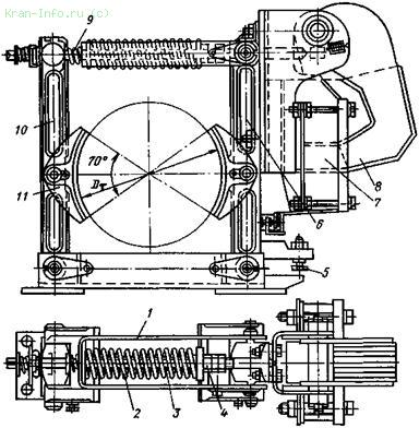
When the termination of the application of torque to the leading coupling half, the springs unclamp the pads up to the stop of the lining in the body of the AMT. When this occurs, braking and stopping of the driving and driven half coupling, and with them the worm of the winch reduction gear of the load lifting (or boom), occur. Since the braking torque generated by friction between the pads and the body is 2.75 times the torque on the worm, for lowering the load (or boom) the half coupling half from the reverse mechanism receives a counterclockwise rotation (as viewed from the cardan's cross). At the same time, the connecting rods begin to pull the pads off the AMT body, compressing the springs. The pressing force of the pads against the body and the friction force of the pads against the body decrease, and the load is lowered at a speed corresponding to the engine speed.
The body of the automatic coupling is attached to the body of the worm gear with six bolts that are kept from unscrewing by spring washers.
Installation of automatic brake-clutches on automobile cranes of AK type instead of permanently closed belt brakes is difficult due to the design features of the winches of these cranes. In this regard, the installation of the coupling-brakes on the in-service valves of the AK type may not be made (letter of the USSR Gosgortekhnadzor No. 06-13-1 / 884 of July 1, 1969). Managers of enterprises and organizations with AK type cranes should organize proper supervision of the condition of band brakes, timely and high-quality repairs to them, ensuring reliable operation.
The plants of the USSR Minmontazhspetsstroy, which produce AK-type cranes, supply them with Bezlepkin's device, which prevents the boom from falling if the brake malfunctions or the tape breaks. Controlled brakes are shoe or tape normally closed or normally open.
Control is carried out using a system of levers (mechanical control), as well as by means of a hydraulic or pneumatic drive. In normally open controlled brakes, when there is no force on the pedals or the control lever, the brake can be opened by the force of a compressed spring. When a force is applied to the pedal or lever, the brake closes and brakes.
Load brakes are automatically closed by the weight of the lifted load. Such brakes are used in hand-operated lifting mechanisms (hand hoists), and sometimes in machine-driven mechanisms.
Load-resistant brakes are of two types: 1) with opening brake surfaces in the process of lowering the load; 2) with non-closing brake surfaces.
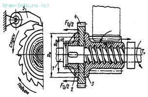
In fig. 5.19 shows a diagram of a conical load-resistant brake of the second type. The brake consists of a conical disk a mounted on a worm shaft, a second disk b equipped with a conical recess, ratchet teeth and a fifth with which it rests against a stationary body c. The body also has a fixed axis of rotation of the dog d. When lifting a load, discs a and b rotate together, held together by friction due to the axial force of the worm, and the ratchet dog slides along the teeth without interfering with the lift.
At the end of the lift, the disks continue to be held together by friction, and the ratchet device prevents them from turning together. To lower the load, it is necessary to overcome the friction force between the discs by applying an external force from the drive.
In addition to the conical disc brake discs are applied; they are equipped with standard electric hoists (telphers).
The requirements for installing brakes are as follows.
1. Installation of brakes on the mechanisms of lifting and changing the boom. These mechanisms should be equipped with normally closed type brakes that automatically open when the drive (engine) is turned on. An exception is allowed for mechanisms equipped with friction, cam and other controlled clutches of inclusion. Such mechanisms are allowed to be equipped with controlled (handle or pedal) brakes of normally closed type, interlocked with the clutch to prevent arbitrary lowering of the load or boom.
In a double-drum gripper winches with a separate electric drive, the brake must be installed on each drive. On the drive of the supporting drum to improve the scooping of the material with a grab, a button (pedal) device is allowed to release the mechanism when the engine is not running; at the same time, the release should be possible only when the driver presses this pedal continuously.
When the electrical protection is triggered or the current is turned off, the brake should automatically close even when the button is pressed. A pedal for releasing the supporting drum is installed, for example, on railroad cranes of the type KDE. During the operation of these cranes with a grab, the crane operator presses the pedal, when the open grab has already touched the material when lowering, the supporting ropes have not yet been loosened. Pressing the pedal to loosen the supporting ropes is made simultaneously with the inclusion of the mechanism of the closing ropes on the rise, i.e. to close the grab.
Mechanisms for lifting cargo and changing the departure of cranes transporting molten metal or slag, poisonous or explosives are equipped with two brakes, acting independently from each other. These brakes should be designed so that in order to check the reliability of braking of one of them it would be possible to easily remove the braking effect of the other.
The mechanisms for the main lifting of well, mite, stripper, and other special metallurgical specks intended for transporting hot metal should also be equipped with two brakes. In this case, the metal should be considered red-hot, extracted from heating furnaces or heating wells for subsequent processing by pressure.
Mechanisms for lifting cranes of general purpose, also used for transporting heated metal, are not supplied with two brakes.
For lifting mechanisms with two drives on each of them must be installed at least one brake. At the same time on the cranes transporting molten metal and slag, poisonous or explosive substances, the drive must have a rigid kinematic connection between them, precluding spontaneous descent of the load when one of them fails (see Fig. & 2. 3).
For general-purpose cranes intended for the transport of ordinary goods, if the lifting mechanism has two drives, they can be operated separately or together.
Mechanisms for lifting electric hoists, designed to transport liquid metal, poisonous or explosive substances, must also be equipped with two brakes. In standard hoists, a load resisting brake is typically used as the second brake. On all lifting mechanisms with a manual drive, an automatically acting load brake must be installed automatically (see Fig. 5. 19). In cases where the installation of two brakes is required on such a mechanism (transportation of liquid metal, toxic and explosive substances), the second brake can be replaced by a self-braking worm pair.
On the mechanisms of lifting cargo and booms of cranes with machine drive, it is impossible to use a self-braking worm pair instead of a brake, since when worn, it loses the ability of self-braking. Gosgortekhnadzor recorded cases of falling arrows of railway cranes of old structures, the mechanisms of which were equipped with such a device.
In case of a pneumatic or hydraulic actuator, a device (non-return valve) should be provided instead of a brake, which excludes the possibility of lowering the load or boom when the pressure in the pneumatic or hydraulic system drops. Such a device should also be used for the mechanism for extending the telescopic boom of hydraulically operated cranes. The use of permanently closed (uncontrolled) brakes for load lifting and change-over mechanisms is not allowed due to the design flaws inherent in these brakes. An exception is allowed when installing such a brake as an additional one. In this case, only the main brake should be taken into account.
By a special decree of the USSR State Technical Supervision Service on the in-use K-32 and LAZ-690 truck-mounted cranes, the brakes are constantly closed and replaced with an automatic clutch-brake. This regulation does not apply to AK cranes that have such brakes.
Gosgortekhnadzor of the USSR also clarified (letter No. 13-15g / 551 of May 4, 1972) that the requirements of the crane owner regarding the replacement of normally open brakes on jib self-propelled cranes of early releases (for example, K-102, K-123, K-124 , K-161) are not presented to the brakes of a normally closed type, except for the case when a crane is being reconstructed.
When choosing the location of the brake should be guided by the following. In the mechanisms of lifting the load and changing the overhang with the unlockable kinematic connection of the drum with the engine, one of the coupling halves of the engine-gearbox coupling located on the gearbox shaft can be used as a brake pulley. For mechanisms with controlled start-up clutches, the brake pulley must be fastened directly to the drum or mounted on a shaft having an independable kinematic connection with the drum. In both cases, if there is a second brake, it can be installed on the motor shaft or on any shaft of the mechanism.
2. Install the brakes on the movement mechanisms. On the mechanisms of movement of cranes with engine-driven brakes must be installed if the crane is designed to work: in the open air (tower, portal, gantry, jib self-propelled and bridge cranes); indoors - moves along a path laid on the floor (for example, a bicycle crane); indoors on the overhead track - moves at a speed of more than 32 m / min (bridge and mobile cantilever cranes). Crane trucks with travel speeds of more than 32 m / min must also be supplied with a brake.
The brakes of these mechanisms, except for automobile, pneumowheel cranes, cranes on a special chassis of the automobile type and rail, should be normally closed type, automatically opening when the drive is turned on.
On automobile and pneumowheel cranes, as well as on cranes mounted on a special chassis of an automobile type, the movement mechanisms can be equipped with a normally open controlled brake provided the parking brake is also installed.
Brakes on the mechanisms of movement of railway cranes must meet the requirements of the Rules of the Ministry of Communications. For braking railway cranes with their independent movement in the frame of the mechanism of movement usually have two shoe electromagnetic brakes. For the transportation of such cranes in the train, they are equipped with automatic brakes (Matrosov's brake). These brakes are activated when the air brake line is broken and when the emergency braking valve is opened.
When the crane moves in the train, the brake system of the crane movement mechanism is disabled by disconnecting the drive wheel pair from the crane movement mechanism and only automatic brakes work. In addition, the frame of the railway crane running platform is equipped with a handbrake, which can brake the crane in the event of a long stop or parking on a slope with the movement mechanism turned off.
3. Install the brakes on the rotation mechanisms. On the mechanisms of rotation of tower, boom with tower-boom equipment and gantry cranes, installation of controlled brakes of normally open type is allowed. With the use of such brakes, the boom of the crane, which is in the non-operating position, spontaneously turns in the wind, thus reducing the wind load on its metal structures.
A normally open type brake must have a device for locking it in the closed position. Such a device is installed on the levers or brake control pedals. On the mechanisms of rotation of the remaining cranes must be installed brakes normally closed type, automatically open when you turn on the drive.
On automobile cranes K-46, KS-2561D and KS-2561E, produced by Balashikha, Drohobych and other factories, the use of permanently closed brakes on the turning mechanism is permitted (Letter of the USSR State Technical Supervision Service No. 06-13-176 / 301 dated March 16, 1971) .
General requirements for brakes mechanisms of rotation and movement.
On cranes equipped with controllers whose electrical circuit provides the possibility of braking the mechanisms of movement or rotation by the electric motor, the brakes may not close when the motor is switched off by control devices. In this case, the electrical circuit may have a button to apply or remove the brake when the controllers are in the zero position. On the mechanisms of movement and rotation, equipped with automatic brakes, it is allowed to equip the brake with an additional drive (mechanical, hydraulic, pneumatic) for smooth braking. In this case, when electric motors are turned off by control devices, the brake may not close. On the mechanisms of movement and rotation with a manual drive brake may not be installed.
Basic data for brake design
The braking torque of the lifting mechanisms is determined from the conditions of reliable holding of the load on the weight in a static state with a certain factor of safety of braking. The braking safety factor is the ratio of the moment created by the brake to the torque generated by the load on the brake shaft and determined taking into account the losses in the mechanism: Lifting brakes, if the Rules provide for the possibility of installing one brake, calculated according to the braking margin. 5. 6.
Table 5.6 Braking Factor
If there are two or more brakes on the lifting mechanism (cranes transporting molten and red-hot metal, poisonous or explosives), they are calculated assuming that the entire load is held by one brake. The braking factor for these brakes must be at least:
1, 25 - if there is one drive with two or more brakes on the mechanism;
1, 25 - if there are two drives on the mechanism with one brake on each drive;
1, 1 - if there are two or more drives on the mechanism with two brakes on each drive.
For electric hoists equipped with two brakes, the braking factor of the electromagnetic brake is taken at least 1, 25, and the load-resisting 1, 1, the braking factor of the braking mechanism of the boom overhang mechanism must be at least 1, 5; while the static moment on the brake shaft, created by the weight of the boom, counterweight, the largest working load and wind when the crane is in working condition, should be determined in the position of the boom at which the moment has the maximum value.
If two brakes are installed on the boom raising mechanism to reduce dynamic loads during braking, the braking factor of one of them should be taken not less than 1, 25, and the second one should be taken not less than 1, 1. The imposition of such brakes should be made automatically. The brakes of mechanisms for movement of bridge cranes operating outdoors and not equipped with special anti-theft devices should be designed to keep the crane (without load) in a stationary state with a braking factor of 1, 2 in the event of a wind acting on the crane, the force of which reaches the rated pressure accepted in accordance with GOST 1451-65 "Cranes. Load wind "for the idle state of the crane.
The brakes of movement of cranes operating on land rail and trackless tracks must ensure that the crane and its cargo trolley are retained (if the crane is equipped with such a trolley) under the maximum permissible wind received according to GOST 1451-65 for the operating condition of the crane, as well as their smooth stop. In this case, a smooth stop should be considered such a stop at which a load suspended at a hook located at a height of 1 m from the ground level deviates from the vertical no more than 0.25 m. It is recommended to take the holding force reserve downwind for these cranes to be 1, 6 .
The turning mechanism brake should stop the turning part of the crane on the allowable braking path of the boom tip when the wind is acting in the direction of the turn and allowable slope and ensure smooth braking in the absence of wind. Wind pressure is accepted according to GOST 1451-65 for the operating state of the crane.
Design requirements for the brakes. The load used to close the brake must be securely fastened to the lever against any displacement or fall. If a spring is installed for this purpose, the brake must be closed using the force of a compressed spring. The spring must be located in the sleeve or provided with a centering rod. The brake must be protected from moisture or oil on the brake pulley.
Brake and stopping devices used to ensure reliable and safe operation of the MRG.
Brakes. They are intended to regulate the speed of lowering the load and keep it on weight, as well as to stop and hold the mechanisms of the PMG in the inhibited state.
Brakes are divided :
· Depending on the purpose: to stop, which are used to completely stop the mechanisms; overflow, limiting the speed of lowering the load, combined, performing those and other functions;
· By the method of control: controlled and automatic, the inclusion of which is made under the influence of centrifugal forces or gravity of the lifted load;
· By the nature of the work: on normally closed (braked when the mechanism is turned off) and normally open.
Brakes must be reliable, reliable in operation, durable, ensure smooth braking during quiet operation, and have minimum dimensions. .
Mechanisms for lifting cargo must be equipped with: normally closed type brakes that automatically open when the drive is turned on and provide a braking torque with a safety factor of braking accepted in regulatory documents, but not less than 1.5.
To reduce the dynamic loads on the boom raising mechanism, it is allowed to install two brakes with a braking factor of one, of which at least 1.1, and the second at least 1.25. In this case, the imposition of brakes should be done sequentially and automatically. In a double-drum gripper winches with a separate electric drive, the brake must be installed on each drive.
With a lifting mechanism with two simultaneously activated drives, at least one brake with a brake reserve of 1.25 must be installed on each drive. In case of using two brakes on each drive and if the mechanism has two or more drives, the safety factor of braking of each brake must be at least 1.1.
The mechanisms for lifting and changing the overhang should be equipped with brakes that have a non-disconnected kinematic connection with the drums; in the kinematic chains of the lifting mechanisms of electric hoists, the installation of limit torque couplings is allowed.
When installing two brakes, they must be designed so that, in order to check the reliability of one of the brakes, you can safely remove the effect of the other brake.
The load, closing the brake, should be strengthened on the lever so that the possibility of its falling or arbitrary displacement is excluded. In the case of springs, the closing of the brake must be made by the force of the compressed spring.
Dry, friction, disk and disc brakes should be protected from direct moisture or oil on the brake pulley. The worm gear cannot serve as a replacement for the brake.
The values of the safety factors of braking for various modes of operation of the mechanisms are presented in Table. 3.8.
Table 3.8
Braking factor
|
Braking factor |
Mechanism of operation mode group |
|||
In lifting machines, two-block brakes are widely used ..

Double Block Brake (ris.3.13) consists of two symmetrical pads 1 and 4 , the upper ends of the levers of which are connected by a strain 2 a pig tie (to regulate its length) and an angle lever 3. Attached to the right hinge of this lever 5 pivotally connected to the lever 6. Hinges About 2 and About 3 in most cases they are combined into one to simplify the design of the brake. Departure of blocks from a pulley is usually prescribed in the range of 0.5 ... 2 mm, depending on the diameter of the brake pulley (with Dt= 100 ... 200 mm waste is made equal to 0.5 mm). With an increase in the diameter of the pulley, the amount of waste increases.
The materials of the working surfaces of the pad and pulley are chosen such that they have the greatest possible friction coefficient. Brake pulleys are usually made of steel (C t 45L, 55L) or cast iron (Sk-15), and the brake pads are made of steel or cast iron. Currently used steel or cast iron pads lined with a special asbestos tape with a thickness of 4 ... 12 mm. Asbestos tape is attached to the block with copper or aluminum rivets or countersunk head bolts.
Angle α the brake pulley girth is usually taken within 60 ... 90 °, and the pad width b = (0.3 ... 0.4) D T.
In order to completely relieve the brake pulley shaft from lateral forces, it is necessary to ensure equality of forces FN 1 = FN 2. For a given brake, this is possible under the condition of equality F 1 and F 2 what can be achieved with an appropriate lever design 3.
An effort gG rrequired for braking, calculated as follows. For a given braking moment T Tand adopted pulley diameter Dtdetermine the value of the circumferential friction force Fton the surface of the pulley, which is evenly distributed between the two pads. Normal force required to create a circumferential force, calculated by the formula:
Effort in pitch 2 equally F / cosφ. Out of balance corner arm 3 find the effort F 5, necessary to create effort F, i.e .:
where G r and G i- the mass of the load and anchor, H; η w - Efficiency hinges lever system.
In the electromagnetic shoe brake with a short-stroke solenoid pads 11 closed with pre-compressed spring 2, which presses right on the stock 3 left lever 10 and left on the bracket 1 right lever 6 (pic.3.14) . Disconnect the pads by the electromagnet 7, mounted on the right lever. When you turn on the current anchor presses on the head of the rod 3 and compresses the spring 2 . Under the action of the moment created by the force of gravity of the electromagnet, the right pad first departs by an amount determined by the adjustable stop 5 and then left 11 under the action of the spring 9 . Spring force 2 nut adjustable 4 .
R and with. 3.14. Brake with short-stroke electromagnet:
1 - bracket; 2 - spring; 3 - stock; 4 - nut; 5 - emphasis; 6 - lever arm; 7 - electromagnet;
8 - anchor; 9 - spring; 10 -lever arm; 11 - block

The disadvantages of electromagnetically controlled brakes include the impossibility of controlling the magnitude of the braking moment in the process of braking and the sudden activation of the brake, accompanied by the impact of the armature on the core. These defects are not in the brake with electro-hydraulic control (Fig.3.15), used to open the brake. In such brakes (Fig.3.15) the braking is performed in the bracket 7 compressed spring 9, which is through stock 8, lever arm 10 and traction 4 pulls together pads 3 and 5 (using levers 2 and 6 ). The brake is discharged using an electro-hydraulic pusher: a small electric motor with a centrifugal pump is placed in the hydropusher piston, which, when it starts up, starts to pump fluid from the cavity above the piston into the cavity below it; piston extends out of cylinder 12, stock 11 raises the left end of the lever 10 and overcoming the force of the spring 9, pushes the levers with pads off the brake pulley. Waste pads adjustable screw 1 .
The use of a spring in the brake for its closure provides compactness and speed, and the use of an electrohydropusher for opening is smooth and great effort.
Automatic normally closed brakes with spring locking, electromagnetic or electro-hydraulic drive types TKT, TKP, TKG, EMT-2 are widely used in the mechanisms for lifting cargo. For groups of operating modes M6, M7, M8, it is recommended to use brakes with electro-hydraulic drive type TKG. As a brake pulley, it is advisable to use one of the coupling half coupling. The main parameters of the brakes of TKT and TKG types are presented in the Appendix (Table A.2 and Table A.3).
Margin Limits :
· Brake pulleys:
Cracks and breaks over working surfaces;
Wear of the working surface of the rim of more than 25% of the original thickness;
· Brake linings:
Cracks and breaks suitable for rivet holes;
Worn brake lining in thickness until rivet heads appear or more than 50% of the original element thickness.
· Brake mechanism:
The absence of individual fastening elements or the weakening of their tightening;
Lack of fluid, leakage of fluid through the seals in the housing of the hydropusher, jamming when triggered, the presence of phase failure.

Load brakes (Fig. 3.16). Applied as a drain brakes, which are automatically closed by gravity of the load. On drive shaft 1 fixedly fixed thrust disk 2 gear is set on the thread 3, the side surface of which is made in the form of a disk. On the shaft between the discs 2 and 3 ratchet mounted freely 4, whose teeth are engaged with the dog 5 . By rotating the shaft 1 in the direction of lifting the gear 3, moving the thread to the left, clamp the ratchet 4, therefore the system 2-3-4 rotates in the same direction and little dog 5 slides along the ratchet teeth. At the termination of raising ratchet 4 stalled dog 5, and the load remains on weight.
Shaft is required for lowering 1 rotate in the opposite direction. With this gear 3 with the disk along the thread will begin to move to the right, the pressure on the side surfaces of the ratchet from the side of the disks will decrease. As soon as the frictional moment between the discs and the ratchet becomes insufficient to hold the gear 3 with a disc against rotation, the load will begin to fall. This will occur as long as the angular velocity of the gear 3 with the disk will not exceed the angular velocity of the shaft 7 . After this, the discs will converge again as a result of the gear moving. 3 left along the thread and stop their mutual angular movement due to increased friction between the disks and the ratchet.
When lifting the load, the ratchet rotates, so the moment from the load is transmitted to the electric motor through the thread and one pair of friction surfaces of the brake discs, ie:
|
|

where F 0- axial force compressing rubbing surfaces, N;
d cp-the average diameter of the thread, m;
α - the angle of the helix thread,
ρ΄ - reduced angle of friction in the thread;
ƒ - coefficient of friction of brake discs;
D cf - average diameter of brake discs, m.
When locking the ratchet does not rotate and friction occurs in two pairs of surfaces; z = 2. Therefore, the braking moment.
§448. The ratio of the smallest diameter of the winding to the diameter of the rope must not be less than:
a) 120 for single-line hoists with a friction pulley;
b) 95 for multi-rope hoists with a deflecting pulley;
c) 79 for guide pulleys and drums of lifting units on the surface and for multi-rope installations without a deflecting pulley;
d) 60 for guide pulleys and drums of underground hoists and winches, as well as for machines and winches used in excavation workings;
e) 50 for mobile hoists, guide pulleys and drum winches used in waste dumps, as well as for hauling winches;
e) 20 for guide pulleys and drums of tunnel cargo winches for suspension of regiments, outboard pumps, pipelines, rescue ladders.
For mobile, auxiliary and shunting winches, as well as for guide pulleys of inclined lifting installations with a pulley angle of circumference up to 15 0, this ratio is not limited.
§449. For cargo-human and human lifting installations on vertical and inclined (more than 60 0) operational shafts, the winding of the rope on the drum must be single-layered.
Allowed:
a) two-layer winding of the rope on the drum - for cargo vertical lifting installations on the surface and during the ascent and descent of people along the workings with a tilt angle of 30-60 0,
b) three-layered winding - when people go up and down along inclined workings with a slope angle of up to 30 0, while passing vertical and inclined workings, for underground cargo vertical and inclined lifting installations and cargo inclined retractable installations on the surface;
c) multi-layered winding - for mobile and auxiliary cargo lifting installations (on waste dumps, racks, etc.) on the surface and underground, as well as low-speed driving tunnels (with a speed not higher than 0.2 m / s) winches.
§450. The drums of the newly installed hoisting machines must have flanges on both sides, with a height of at least 1.5 times the diameter of the rope. The winding surface of the drums should have cut spiral grooves regardless of the number of layers of winding.
If there is more than one layer of winding ropes on the drum, the following conditions must be met:
a) the flange of the drum should protrude above the top layer 2.5 diameters of the rope;
b) a critical section of the rope with a length of a quarter of the last turn of the lower row (transition to the upper row) should be enhanced observation (taking into account the wires broken in this place) and the rope should be moved a quarter of a turn every 2 months.
§451. The attachment of the rope to the drum must be made so that when the rope passes through the slot in the cylinder of the drum it does not deform with the sharp edges of the slot. Do not attach the end of the rope to the shaft of the drum. Fastening of the ends of the rope to the drum is made to devices specially provided for on the drum, allowing to fasten the rope in at least three points.
To loosen the tension of the rope in the place of its attachment to the drum on the surface of the latter must be at least three turns of friction on the drum lined with wood or press, and at least five turns of friction on the drums not lined with friction materials. In addition to friction turns, there should be spare turns for periodic testing of the rope. Spare turns can be located both on the surface of the drum and inside it. Reels designed to accommodate spare turns of the rope must have special devices that allow them to be fixed relative to the drum of the machine.
§452. The lining segments of the drive pulleys of lifting units with friction pulleys and pile pulleys must be attached so that there are no connecting parts on the edges of the lining groove that, if their attachment is broken, could fall into the groove under the rope. Bolts securing the lining should be inspected weekly. The unusable bolts found at the same time are subject to immediate replacement by new ones. The ribs of the guide pulleys and pulleys of friction of newly manufactured machines must protrude above the upper part of the rope by at least 1.5 of its diameter.
Lining segments should be replaced with new ones when they are worn out to a depth of one diameter (without taking into account the initial dimple), to the side - to half the diameter of the rope.
Lining segments must be replaced with new ones also in the event that the residual height of its wear result turns out to be 0.75 of the rope diameter. Scraper pulleys must have an ice removal device, the design of which is determined by the project.
§453. Pulleys with cast or stamped rims that do not involve the use of lining should be replaced with new ones or restoration by surfacing using a process map developed by a specialized organization when the rim or flange is worn to 50% of their initial thickness.
Before weighting a new rope and subsequently at least once a quarter, the pulleys are subject to inspection by the chief mechanic of the mine or his assistant; at the same time the groove section is measured. The results of the inspection are recorded in the “Log of the results of the inspection of the lifting installation” with a sketch of the section of the groove of the pulley of the most worn-out area.
§454. The maximum speed of ascent and descent of people in vertical workings is determined by the project, but should not exceed 12 m / s.
§455. The highest speed when lifting and lowering loads on vertical workings is determined by the project.
§456. During the ascent and descent of people along inclined workings, the highest speed of movement is determined by the project, but should not exceed 5 m / s.
When lifting and lowering loads on inclined workings, the maximum speed should not exceed:
a) when lifting cargo in skips - 7 m / s;
b) when lifting loads in trolleys - 5 m / s.
§457. During the ascent and descent of people in buckets along the guideways, the maximum speed should be no more than 8 m / s, and in places where there are no guides, no more than 1 m / s.
§458. When lifting and lowering cargo in buckets on guides, the speed of movement of buckets should not exceed 12 m / s, and in places where there are no guides, 2 m / s.
§459. For lifting installations of all types of vertical and inclined (above 30 0) openings, the deceleration of the lifting vessels should not exceed 1 m / s 2, and for workings with a slope of up to 30 0 - 0,7 m / s 2. For vertical lifting installations and inclined (over 30 0) openings intended for lifting and lowering people, the acceleration should not exceed 1 m / s 2, and for openings with an inclination angle up to 30 0 - 0.7 m / s 2.
The magnitude of the acceleration for cargo lifting installations is determined by the project.
Acceleration and deceleration of the lifting vessels when driving trunks in the sections of motion without guides and when unloading the tubs should be no more than 0.3 m / s 2, and when choosing a rope inlet, when lifting a tub to calm and when landing it on the face - 0.1 m / s 2.
§460. To protect against overshooting and overspeed, the shaft lifting installation must be equipped with the following safety devices:
a) for each lifting vessel (counterweight) with a limit switch mounted on a scraper designed to turn off the lifting machine and activate the safety brake when lifting the vessel 0.5 m above the level of the receiving platform (its normal position during unloading), and two limit switches, installed on the depth gauge or on the cruise control and designed to duplicate the operation of the limit switches installed on the scraper. In inclined workings, limit switches should be installed at a distance of 0.5 m from the stopping point: human trolleys - when people are landing on the upper landing site; cargo party - before lowering it into a sloping ride.
Lifting units with tilting stands should have additional limit switches mounted on the rammer 0.5 m above the level of the site intended for landing people in the cage. The operation of these limit switches must also be duplicated by limit switches mounted on the depth indicator (travel regulator).
It is allowed to install duplicate limit switches on the scraper on the same level as the main ones when they are powered with separate cables and for installing on the machine control panel for each of them separate buttons (without fixing the position) intended for checking the operability of the switches. Additional limit switches (main and backup) on hoisting installations with tilting stands should be included in the protection circuit depending on the given signal "load" or "people";
b) a device that turns off the installation in case of exceeding the maximum speed of a normal stroke by 15%;
c) a speed limiter that prevents the vessel from approaching the receiving sites at a speed of more than 1.5 m / s during the lowering-lifting of the load and 1 m / s during the descent-lifting of people and is triggered when the speed of the approach of the vessel exceeds 15%. During the period of deceleration with the most severe mode of safety braking, the speed limiter must not allow over-lifting and hard landing of the lifting vessels (this requirement applies to newly mounted lifting installations that have an equal speed of more than 2 m / s and operated at a speed of more than 3 m / s) ;
d) shock-absorbing devices installed on the scraper and in the sump (applies only to multi-rope lifts).
§461. Mine lifting installations must be equipped with the following protective and interlocking devices:
a) maximum and zero protection, acting when the motor is overloaded and the absence of voltage;
b) protection against sagging strings and rope inlet in the barrel;
c) blocking of safety arrays of trunks at receiving sites, including the “Stop” signal from the driver with open grids and preventing the opening of the grids in the absence of a stand on the receiving platform of the horizon. The deadline for the introduction of the lock, which does not allow the opening of the gratings in the absence of a cage on the horizon receiving platform, is set by the administration of the enterprise in coordination with the local bodies of the state mining and technical inspection;
d) a lock allowing the engine to be turned on after the vessel has been lifted only in the direction of the elimination of the lift;
e) arc interlocking between reverse contactors, as well as dynamic braking;
e) a lock to prevent the safety brake from being removed if the operating brake lever is not in the “braked” position and the control unit (controller) handle is in the zero position;
g) blocking, which, when sinking the barrel, stops the tub for 5 m before approaching it to the working shelf during the erection of lining and at the approach to the bottom of the trunk;
h) protection from hovering of vessels in the discharge curves;
and) blocking from sliding ropes.
§462. Lifting machines and winches should be equipped with an apparatus (indicator) showing the position of the vessels in the barrel to the driver, and an automatic bell signaling the need to start a period of deceleration.
On hoisting machines and winches intended for equipment suspension when driving vertical shafts, the depth indicator is not required.
§463. Each lifting machine to the winch should be provided with working and safety mechanical braking with the drive independent from each other. These types of braking can be carried out with one or two brake actuators.
In newly created hoists and winches, braking must be carried out by two brake actuators. Brakes (including manual) should be located so that the driver could freely control them without leaving the workplace.
§464. In the sinking cargo winches and winches for rescue ladders the following should be provided: shunting brake on the motor shaft or intermediate shaft, safety brake, ratchet stop on the drum and blocking that prevents the electric motor from running in the direction of descent when the safety brake and locking device are on. Manual winches intended for lowering equipment and materials must have: a brake, a stopper ratchet device and a dual gear train.
For winches in auxiliary workings for the descent and lifting of equipment, woods and other materials, as well as when driving inclines, bremsberg and their walkings with tilt angles up to 30 0, one brake is allowed. In the shafts of the mines, where several lifting installations are located, on the control panel of each of them there should be a button for simultaneous emergency shutdown of all lifting machines.
§465. Safety braking of the hoist must be carried out with a load or springs. The number of springs involved in creating the braking force should be such that when one of them breaks, the braking force as a whole does not decrease by more than 15%.
For cargo-lifting systems with spring drives, the presence of two drives is required.
The safety brake actuator must be shoe-type (disk) type. Installation of brake pulleys on the motor shaft or on the intermediate shaft is allowed only for service braking. In this case, the executive body can be shoe-type (disk) or tape type.
The executive body of the safety braking device must act on the brake pulleys, which must be located on the shaft of the coiled body and fastened to the rim of this body. Safety braking must be carried out both by the driver and automatically. The activation of the safety brake must be accompanied by an automatic disconnection of the lifting motor from the network.
In road winches with a carrying capacity of up to 10 tons inclusive, it is allowed to use a band brake on a drum with a cargo drive and manual release. For auxiliary cargo winches, not intended for the constant lifting and lowering of the load on the trunk, manual braking is allowed.
§466. In addition to the brake, in case of adjusting the position of the drums or repairing the braking device, each lifting machine must have a special locking device. When using drums that allow them to be remotely detached from the shaft (in order to regulate the relative position of the lifting vessels), a lock should be provided to ensure the preliminary locking of the released drum.
§467. For small hoisting machines with a speed of not more than 4 m / s and with a winding body with a diameter of not more than 2.5 m, as well as for active hoisting machines with a winding body with a diameter of up to 3 m, the braking of the service brake is allowed if a load drive is used for working braking . The braking load of the operating brake shall provide a braking torque of at least 1.5 times the maximum static torque. In all other cases, the use of an adjustable service brake with a mechanical drive is mandatory.
§468. With vertical and inclined rises with an angle of inclination above 30 0, the braking torque during safety braking must be at least 3 times the static torque when lifting or lowering the load calculated for the machine. The working brake should, if necessary, ensure the possibility of obtaining the braking torque of the same magnitude. When the angles of inclination are less than 30 0, the braking torque during safety braking must correspond to the values given in table. 7
For workings with a variable angle of inclination, the magnitude of the braking moment is set to the greatest angle of inclination of this output. The value of the coefficient K for intermediate angles of inclination, not listed in Table. 6 is determined by linear interpolation. The braking moment of driving cargo winches and winches for rescue ladders must be at least 2 times the static torque when lifting or lowering the maximum load calculated for the vehicle, and for cargo human (human) driving winches and machines, the braking torque must be at least 3 short relative to the static moment corresponding to the largest possible number of people in the tub. In the presence of two separate drives of working and safety braking, the possibility of the occurrence of braking torque exceeding the calculated one should be excluded, due to the addition of the moments created by them during joint action.
When rearranging the idle drum, the braking device should develop on one brake pulley a braking torque equal to at least 1.2 static torque generated by the weight of the lifting vessel and one branch of the rope.